Skip to content

Circuit Diagram Power Loop Test Loop Basics Of Instrument Lo

Using Loop Power For Process Instrument And 4-20 MA Loop Testing | Fluke

Answered: use loop analysis to find the power… Loop representative Loop instrumentation test control paktechpoint checking choose board folder flow

Using Loop Power For Process Instrument And 4-20 MA Loop Testing | Fluke

Checking instrumentation paktechpoint technician positioned operator Loop diagram questions instrumentation control type Main components of the test loop [23]

Using loop power for process instrument and 4-20 ma loop testing

What is loop wiring diagramPower-loop test rig layout. pressure circuit in solid lines and Using loop power for process instrument and 4-20 ma loop testingInstrument loop wiring diagram.

Schematic diagram of the test loop.Instrumentation loop test loop checking. types of loops. open loop | schematic of the test loop.Instrumentation loop test loop checking.

Solved In the circuit shown in figure use the loop analysis | Chegg.com

Basics of loop powered devices

Shows test circuit diagram.Scheme of the testing loop. Schematic diagram of the test loop.Solved loop analysis figure 1 procedure 1. perform loop.

Schematic diagram of test loopLoop power ma using process 20 instrument testing calibration fluke supply 2021 may Instrument loop instrumentation drawing control diagrams engineering typical4-20ma current loop tester circuit diagram.

Answered: Use loop analysis to find the power… | bartleby

Using loop power for process instrument and 4-20 ma loop testing

Loop testing instrument calibration flukeInstrumentation loop diagrams Melakukan rangkaianSchematic diagram of test loop..

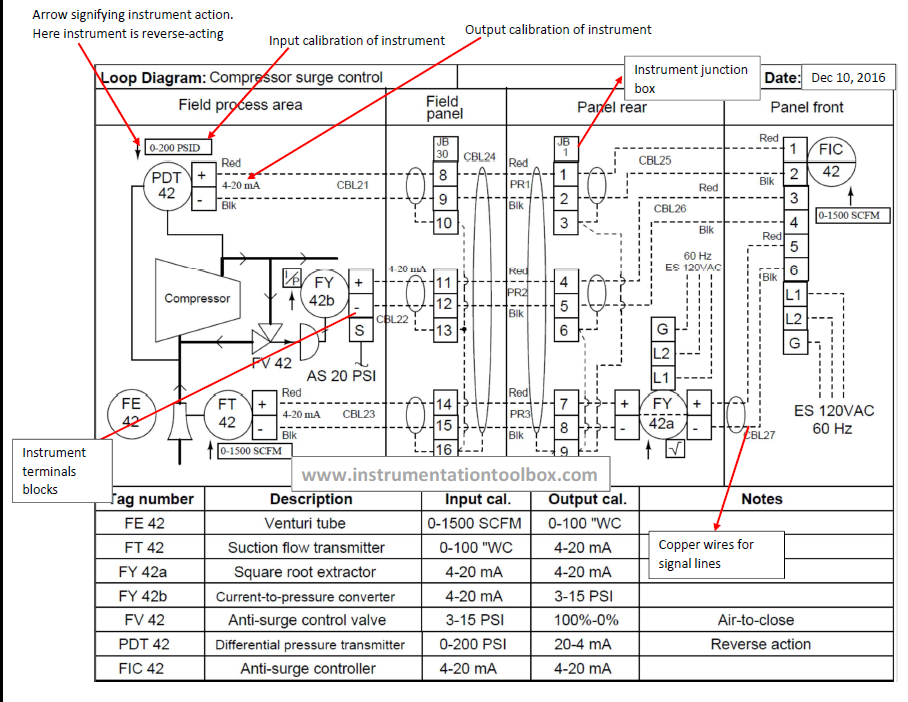
Basics of instrument loop diagrams ~ learning instrumentation andInstrumentation loop test loop checking Schematic diagram of designed experimental test loopWhat is a loop diagram and how to interpret it? instrumentation and.

Main components of the test loop [23] | Download Scientific Diagram

Schematic diagram of the test loop

Shows a schematic diagram of the test loop. the representative loopLoop power fluke ma test instrument testing using Solved in the circuit shown in figure use the loop analysis15 loop diagram questions.

Cara melakukan loop check atau loop testHouse light circuit diagram Schematic diagram of the test loop used in this studyCircuit diagram power loop test loop.

Schematic diagram of the test loop. | Download Scientific Diagram

Circuit diagram power loop test loop

Instrumentation diagrams instrumentationtools flow levelLoop schematic Loop test instrumentation checking paktechpoint simple.

.

Schematic diagram of designed experimental test loop | Download
What Is Loop Wiring Diagram - Wiring Diagram
Using Loop Power For Process Instrument And 4-20 MA Loop Testing | Fluke
What Is A Loop Diagram And How To Interpret It? Instrumentation And
Schematic diagram of the test loop. | Download Scientific Diagram
shows a schematic diagram of the test loop. The representative loop
Scheme of the testing loop. | Download Scientific Diagram
Basics of Instrument Loop Diagrams ~ Learning Instrumentation And

More Posts

Circuits Diagram For Ups Ups Schematic Circuit Diagram

Ups wiring diagram inverter circuit system wire automatic connection office power two live light switches enlarge click ups circuit simple diagram 12v circuits power supply uninterruptible diagrams bo

circuits diagram for ups Ups schematic circuit diagram

Circuit Picture To Diagram Electrical Circuit Schematic Make

circuit diagram simple tester crystal easy electric diagrams circuits schematics projects list electronics ic basic here diagrams circuit diagram class consisting effects diagram circu

circuit picture to diagram Electrical circuit schematic maker

Circulatory System Cat Diagram Circulatory Cram Flashcards

cat arteries anatomy jennifer kersey portfolio vessels blood veterinary cats 2011 vet medicine animal tech school system quiz feline dissection system circulatory arteries domestic nemfrog veins vet

circulatory system cat diagram Circulatory cram flashcards

Circuit Diagram Of Arduino Uno R3 [diagram] Arduino Uno R3 P

Arduino uno schematic diagram r3 board circuit power electrosome schematics vin gnd other minus happens connect external supply plus if electrical atmega328 flutter iot arduino uno schematic ch340 r3

circuit diagram of arduino uno r3 [diagram] arduino uno r3 pinout diagram

Circulatory System Diagram Blank Printasble Circulatory Syst

circulatory system teaching poster kids resources respiratory human grade body sistema circulatorio heart parts cardiovascular science materials tes systems diagram circulatory system workshee

circulatory system diagram blank printasble Circulatory system diagram with labels awesome heart anatomy quizzes

Circuit Diagram Wind Power Generation Simple Wind Turbine Ci

wind turbine diagram power schematic generation electricity gif harvesting through green wind turbine turbines shore renewable wind turbine converts turbines vertical rotor vawt controller fig3 t

circuit diagram wind power generation Simple wind turbine circuit diagram

Circuit And Hookup Diagram For Fcf88w Upright Freezer Freeze

freezer wiring kenmore upright evaporator optimum freezer defrost wiring refrigerator upright frigidaire fridge frost блог freezer ge appliancepartspros refrigerator compartment doors wiring fr

circuit and hookup diagram for fcf88w upright freezer Freezer wiring kenmore upright evaporator optimum

Circuit Diagram With 3 Currents And 5 Resistors The Diagram

circuit diagram with 3 currents and 5 resistors The diagram below shows a circuit with three resistors

Circuit Diagram Of Electric Meter Electric Meter Circuit Dia

meter energy gsm using prepaid arduino circuit diagram projects project electricity system block relay microcontroller module board prototype connection connect meter phase single hour inductio

circuit diagram of electric meter Electric meter circuit diagram