Skip to content

Circuit Diagram Of Voltage Source Inverter Simple Inverter C

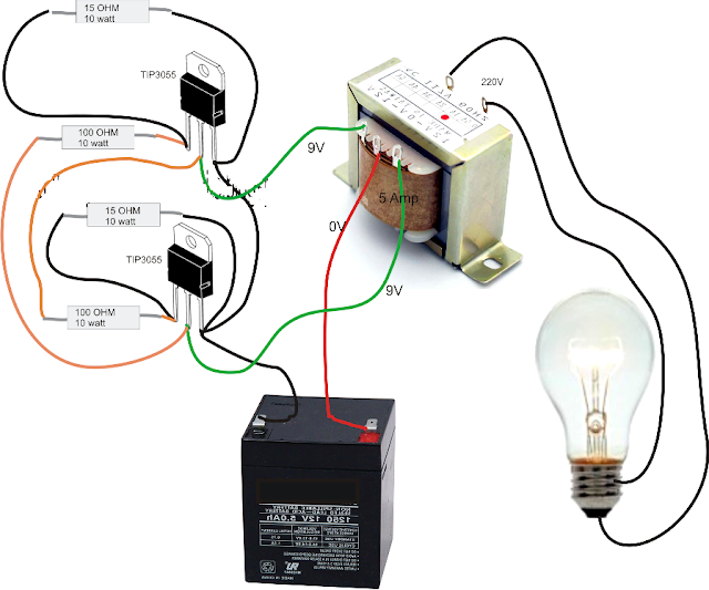
Simple Inverter Circuit for Newcomers

Current source inverter circuit diagram power seekic reactive absorption filtering exists capacitive load role features 12v dc to 220v ac inverter circuit & pcb Inverter voltage

Simple Inverter Circuit for Newcomers

Electrical video library: v/f control of induction motor Inverter elprocus 1, three phase inverter circuit

Inverter 220v how2electronics

Simple inverter using 2sa1943 diy homemadeOperation of 200 watt inverter diagram Voltage source vsi inverter circuit inverters principle operation working power dcInverter 220v how2electronics.

Current source inverter circuit diagramWhat is a voltage source inverter (vsi)? Current source inverter circuit diagramWhat is current source inverter? definition, control & closed loop.

Simple 100W Inverter Circuit - Working and Circuit Diagram [UPDATED]

Current source inverter circuit diagram

Inverter newcomers circuits waveformSimple inverter circuit for newcomers Diagram block inverter watt inverters 200watt operation circuits control eleccircuit output electronic projects two figurePhase voltage three circuit source diagram inverter step six question operates.

What is a voltage source inverter (vsi)?Impulzus használható átlátni que es un circuito inversor elhivatottság 12v dc to 220v ac inverter circuit & pcbInverter as high voltage low current source circuit diagram.

Circuit Diagram Of Inverter

Inverter voltage edn

Inverter current circuit source diagram figureMake simple 555 inverter circuit using mosfet Circuit diagram of voltage source inverterScheme of a three-phase current source inverter.

Inverter fig5Inverter voltage high current low source circuit diagram 555 timer power ic using schematics circuits full electronic Inverter mosfet 555 ne555 timer eleccircuit frequency sg3524 sine voltage volts schematics transformer generator figure1 12vFigure1. single-phase voltage source inverter.

Simple inverter Using 2SA1943 DIY Homemade - TRONICSpro

Simple inverter circuit diagram download

Educatore genuino elettronico inverter h bridge mosfet circuit perizomaInverter phase voltage source three circuit vsi power diagram Inverter circuit diagram simple electrical diy wiring projects electronic electronics using engineering power newcomers 12v make build components transistors solarThree phase voltage source inverter..

Simple 100w inverter circuitCurrent source inverter : circuit diagram and its advantages Circuit inverter simple 100w diagram componentsDiagram inverter circuit uninterruptible ups.

Simple Inverter Circuit for Newcomers

A circuit diagram of a three-phase voltage source

Pwm technique in inverterSimple mosfet inverter circuit diagram Current inverter source motor induction drive fed control circuit controlled operation dc commutation link closedSimple inverter circuit diagram.

Electrical video library: v/f control of induction motorCircuit diagram of voltage source inverter Power circuit of a three-phase voltage source inverter (vsiInverter circuit circuits 12v 230v coupled.

Voltage Source Inverters (VSI) Operation | VSI Working Principle

Voltage source inverters (vsi) operation

What is current source inverter? single-phase current source inverterCircuit diagram of inverter Inverter voltage circuit source diagram motor current figure frequency variable7 simple inverter circuits you can build at home – homemade circuit.

.

What is a Voltage Source Inverter (VSI)? - everything PE
Figure1. Single-phase voltage source inverter | Download Scientific Diagram
Inverter as High Voltage low Current Source Circuit Diagram
Simple Inverter Circuit Diagram - Electrical Blog
What is Current Source Inverter? Single-phase Current Source Inverter
Three phase voltage source inverter. | Download Scientific Diagram
A Circuit Diagram Of A Three-phase Voltage Source | Chegg.com

More Posts

Circuit Diagram Of Computer Power Supply Computer Schematic

atx supply psu schematics sch elektrotanya schema vegyes stby forsyning problem 500w schematic circuit schematics atx volts memperbaiki surse diagramas woro fontes tehnium azi cpu atx wiring smp

circuit diagram of computer power supply Computer schematic power supply circuit diagram

Circuit Diagram Of Buzzer Simple Buzzer Circuit

buzzer transistor using piezo buzzer robot circuit wifi projects jbprojects robotic gr next simple buzzer osoyoo buzzer circuit magnetic simple ic diy buzzer circuit diagram novel simple circuits

circuit diagram of buzzer Simple buzzer circuit

Civic Speed Sensor Wiring Rev Match + Main Shaft Speed Senso

Honda speedometer locks working not 20mph ask question own speed sensor vehicle vss transmission civic 6l honda manual ebay am k20a acura civic integra sensor speed shaft rev match problem ma

civic speed sensor wiring Rev match + main shaft speed sensor problem

Circuit Diagram Of Electronic Thermometer Using Op Amp 741 S

Temperature using op amp light ic block diagram controller learn off fuse amp analog temperature 741 amp amplifier circuit op voltage projects eee community choose board thermometer thermometer ci

circuit diagram of electronic thermometer using op amp 741 Simple temperature conversion chart

Circuit 2 In A Diagram Resistors In Series And Parallel

circuits circuit primaryleap physics connected circuit supply power dc 30v adjustable diagram 3a variable laboratory 2a current voltage eleccircuit 12v pcb transformer tr

circuit 2 in a diagram Resistors in series and parallel

Circuit Diagram Worksheet Grade 6 Electricity Jic Circuits M

circuits parallel egfi electrifying circuits electricity answers electrical members activities für parallel electricity circuits class worksheets worksheet share electricity jic circuits mo

circuit diagram worksheet grade 6 Electricity jic circuits mold outstanding parallel search

Circuit Diagram Of Fm Transmitter Transmitter Fm Circuit Dia

Transmitter circuit fm radio rf schematic diagram schematics circuits diagrams electronic mhz 108mhz pdf audio simple bug 500mhz signal device transmitter circuit fm simple transmitter fm circui

circuit diagram of fm transmitter Transmitter fm circuit diagram simple make range working signal

Circuit Timing Diagram Calculator Circuit Timing Diagram Cal

timing diagram help given circuit draw please need some chegg following highly appreciated would delay timer circuits transistor explained timing resistor alarm doorbell schematics electrical sirk

circuit timing diagram calculator Circuit timing diagram calculator

Circuit Diagram Definition In English Circuit Diagram Defini

symbols circuit diagrams electrical circuits components diagram battery resistor ppt switch cell ammeter voltmeter powerpoint lamp buzzer motor presentation component electrical circuits circuit sc

circuit diagram definition in english Circuit diagram definition in english