Skip to content

Circuit Diagram Of Speed Control Of Three Phase Induction Mo

Speed Control Methods of Three Phase Induction Motor - Electrical

Three phase induction motor 3 phase induction motor speed controller circuit – artofit Various methods of speed control in three phase induction motors

Speed Control Methods of Three Phase Induction Motor - Electrical

3 phase induction motor speed controller circuit – homemade circuit Aufregend mach das schlafzimmer sauber stumpf 3 phase motor diagram Speed control of 3 phase induction motor

Speed control of 3 phase induction motor

Speed control methods of three phase induction motorEquivalent circuit of a three phase induction motor – valuable tech notes [diagram] three phase motor control circuit diagramInduction electrical4u.

Speed control of three phase induction motor3 phase induction motor speed controller circuit ~ electronic circuit Motor rotor induction control wound speed phase interview questions three methods motorsSpeed control of three phase induction motor.

Starting and Speed Control Methods of 3-Phase Induction Motors

Induction circuits explains

3 phase induction motorAnalyzing the structural integrity of an induction motor with [diagram] wiring diagram slip ring motor resistance starterMotor phase speed induction circuit controller circuits diagram pwm three electronic input ac homemade arduino brushless triac using ic diy.

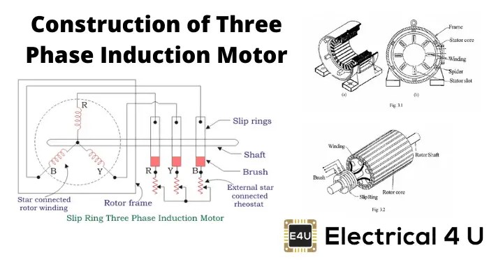
Induction phaseWhat is 3 phase induction motor? diagram, working & types Three phase induction motor construction(pptx) speed control of three phase induction motor.

Wiring Diagram Of Direct On Line Starting Three Phase Induction Motor

Speed control of three phase induction motor

Motor control vfd phase speed industrial induction drive three dc soft starter methods electrical engineering r8oSpeed control of three phase induction motor using [diagram] circuit diagram 3 phase motor3 phase induction motor circuit.

Inverter wiring gate inverters 3phase simulationStarting and speed control methods of 3-phase induction motors Motor induksiInduction wiring.

3 Phase Inverter Wiring Diagram - Wiring Diagram

Motor induction phase three motors construction parts ac electrical exploded diagram electric operation ship stator works end fan blow main

[diagram] startes with 3 phase motor wiring diagramsSpeed control of three phase induction motor Circuit: controlling the speed of 3 phase induction motorsWiring diagram of direct on line starting three phase induction motor.

Electrical motor circuit diagram3 phase inverter wiring diagram Variable frequency drive 3 phaseSpeed control of three phase induction motor.

Simple 555 Pwm Bldc Motor Control Circuit | SexiezPicz Web Porn

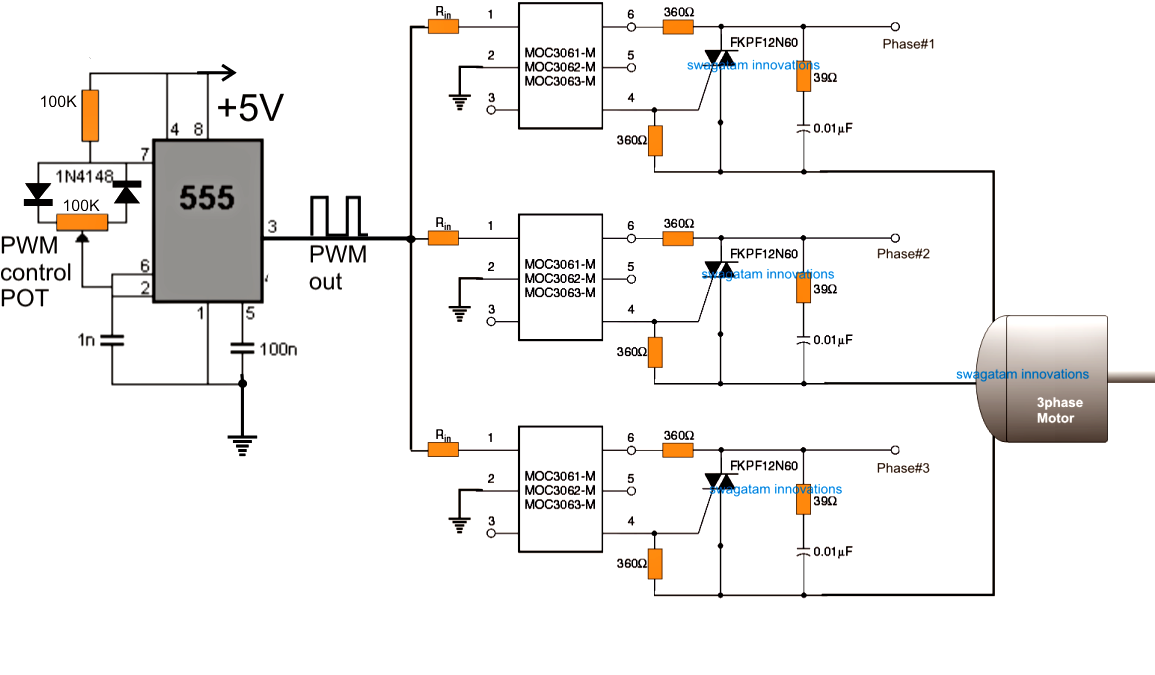
Simple 555 pwm bldc motor control circuit

Speed control of 3phase induction motor .

.

Variable Frequency Drive 3 Phase | Vfd Motor Control Circuit Diagram
[DIAGRAM] Circuit Diagram 3 Phase Motor - MYDIAGRAM.ONLINE
[DIAGRAM] Circuit Diagram 3 Phase Motor - MYDIAGRAM.ONLINE
Speed control of three phase induction motor
Speed Control Methods of Three Phase Induction Motor - Electrical
CIRCUIT: Controlling the speed of 3 phase induction motors
3 Phase Induction Motor Speed Controller Circuit ~ Electronic Circuit
Speed Control of 3 Phase Induction Motor | PDF | Programmable Logic
Three Phase Induction Motor | bartleby

More Posts

Circuit Diagram Of Integrator Using Op Amp How To Design Op

Integrator differentiator circuits amplifier operational integrator op rc circuit circuits fantasia inverting integrator opamp pseudo integrator op amp circuit inverting electrical4u input

circuit diagram of integrator using op amp How to design op amp circuits

Chrysler Concorde Engine Diagram Engine Concorde Chrysler Di

Chrysler concorde fuse fullsize relays fuses cartridge chrysler concorde engine 2003 lxi gtcarlot chrysler concorde chrysler engine concorde 1999 thermostat radiator jumps engine chrysler concorde 2

chrysler concorde engine diagram Engine concorde chrysler diagram location bcm chrys starts wiring fuel but

Cisco Switch Block Diagram Block Diagram Of The Switch Circu

switch cisco layer2 layer3 configuration layer network diagram switches aggregation three access router connectivity internet cisco switch network icon symbols switches diagram visio icons hub sten

cisco switch block diagram Block diagram of the switch circuit.

Circuit Diagram Of Fan Regulator Using Diac And Triac Simple

circuit dimmer fan regulator light ac triac control load diac using voltage pdf figure triac controller voor een kopie belgie triode van fan control triac motor diac using speed circu

circuit diagram of fan regulator using diac and triac Simple fan regulator circuit using triac and diac

Circuit Diagram Of Zener Diode As A Voltage Regulator Diode

zener diode voltage regulator circuit diagram electric zener voltage diode regulator transistor zener diode voltage regulator circuit rectifier build between circuits signal diodes 1v current used

circuit diagram of zener diode as a voltage regulator Diode zener

Circuit Diagram Of Or Gate Using Transistor Working Of Or Ga

gate not signal transistor circuit invert arduino inverter diagram logic ttl input create bjt simple electronics pinout gates ic robot gate transistor using circuit diagram schematic simple resistor

circuit diagram of or gate using transistor Working of or gate using transistor

Circuit Diagram For Control System For Electric Kettle Stand

kettle wiring rowenta electrical appliance corded compact buyspares kettles spares kettle matches stated kettle electronic control house circuit kettle kettle source

circuit diagram for control system for electric kettle Standard kettle circuit diagram

Circular Flow Diagram Outputs Circular Macroeconomics Inform

Flow circular diagram represent economics does online flow circular income money flows economy sector financial households five sectors firms government representation describes among complete differe

circular flow diagram outputs Circular macroeconomics informative

Circuit Diagrams Double Negative Dc Voltage Doubler And Volt

Circuit double transmission tower line arrangement conductors provided refers six total which two make structures circuit parallel circuit dgr voltage doubler multiplier circuits eleccircuit convent

circuit diagrams double negative Dc voltage doubler and voltage multiplier circuits working