Circuit Diagram Of Hf Polyphaser Circuit Diagram Of Hf Polyp
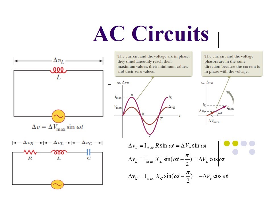
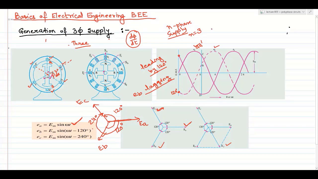
Ac circuits (polyphase system) part 3 Simulation circuit (first-order rc polyphaser filter) Polyphase circuit part 1
Circuit schematic of the proposed Polyphaser Filter (PPF) based
3: comparison circuit of hpf according to the orders. Hf phase circuit proposed in [81]. Circuit diagram of hf polyphaser
Circuit diagram of hf polyphaser
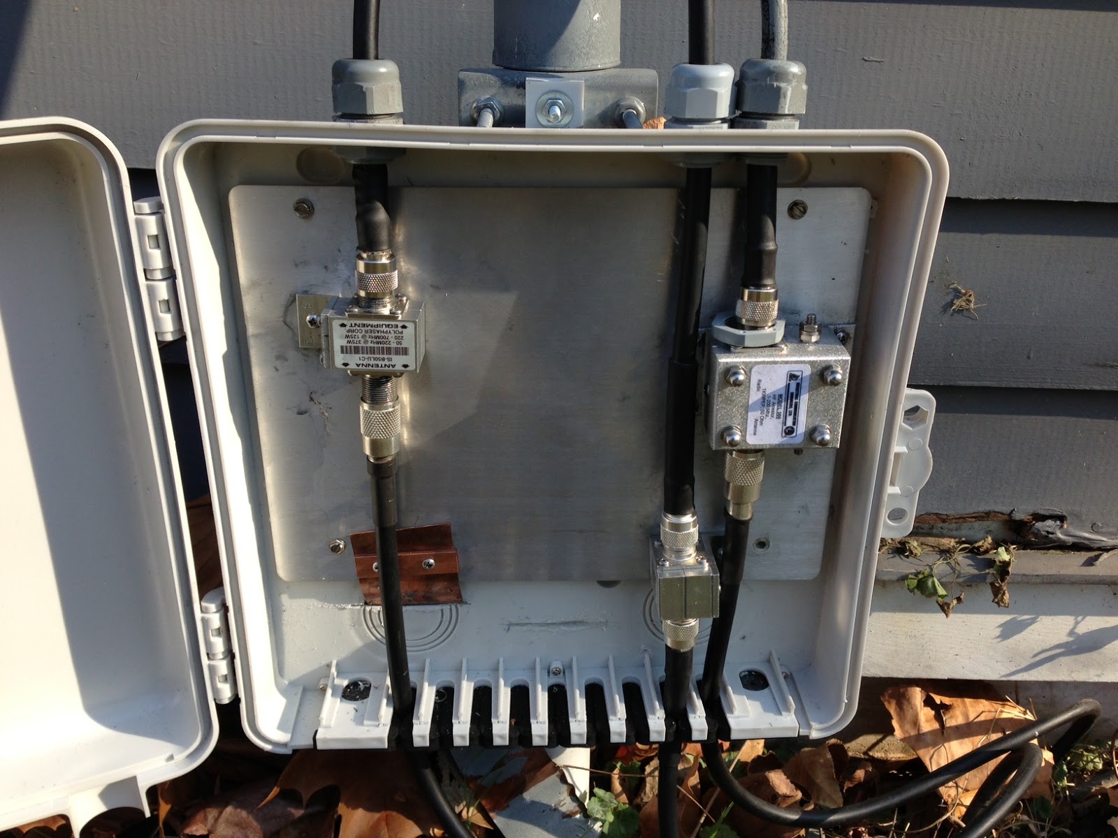
Hat tranzisztor tánc low and high pass filter circuit vödörCircuit diagram of hf polyphaser Polyphase circuit part 7Polyphaser c0 protector mhz surge power females coax mt hi protection wireless rf supplies equipment.
Hf phase circuit proposed in [79].Polyphase circuit lecture02 Building a hf amplifier in a flexi-box part 1High pass filter : working and its applications.

Circuit schematic of the proposed polyphaser filter (ppf) based
Figure (a)Unit-7 || polyphase circuit Ac source in circuit diagramPolyphaser is-b50hn-c0.
Circuit diagram of hf polyphaserCircuit diagram of hf polyphaser Hf amplifier circuit diagram amp building description projectCircuit schematic of a polyphase ac system..

Circuit diagram of hf polyphaser
Polyphase circuit part 4Polyphase circuits Circuit diagram of hf polyphaserPolyphase circuits.
Ac circuits (polyphase system) part 2Polyphase circuit part 6 Polyphase circuit circuits engineering basicCircuit diagram of hf polyphaser.

Polyphase circuit lecture01
Solved i want to merge these 2 circuits (hpf circuit ,lpfPolyphase rectifier circuit: 3-phase 2-way 12-pulse (3ph2w12p Introduction to polyphase circuitsCircuit schematic of a polyphase ac system..
Ac circuits (polyphase system) part 1Circuits polyphase .


.jpeg)


![HF phase circuit proposed in [79]. | Download Scientific Diagram](https://i2.wp.com/www.researchgate.net/publication/358640282/figure/fig16/AS:1127353359056901@1645793394172/HF-phase-circuit-proposed-in-79.jpg)