Skip to content

Circuit Diagram Of Half Wave Rectifier With Capacitor Filter

Single Phase Half Wave Rectifier Circuit Diagram Theory Applications

Question #38f0d + example Half wave rectifier circuit with diagram Wave half rectifier capacitor filter circuit diagram voltage diagrams operation output full waveform working rectifiers tube diode bridge smoothing low

Single Phase Half Wave Rectifier Circuit Diagram Theory Applications

Rectifier wave half full circuit diagram diode rectification crystal operation connected used ac supply shown below through Rectifier circuit diagram Bridge rectifier circuit diagram and waveform

Single phase half wave rectifier circuit diagram theory applications

Rectifier capacitor output waveform rectifiers notice diodeRectifier circuit with capacitor Rectifier capacitor basics pulsating electrical4uWhat is half wave and full wave rectifier?.

10 rectifier circuit diagram robhosking diagramHalf rectifier capacitor rectifiers output waveform diode transformer Half wave bridge rectifier circuit diagramRectifier waveform.
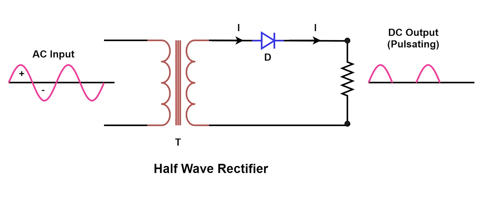
Single Phase Half Wave Rectifier Circuit Diagram Theory Applications

Basics of half wave rectifier

Half wave bridge rectifier circuit diagramHalf wave rectifier – circuit diagram, theory & applications Scr half wave rectifier circuit diagramHalf wave rectifier basics, circuit, working & applications.

Onclick786: rectifier,half wave rectifiers,half wave rectifier with .

Rectifier Circuit Diagram | Half Wave, Full Wave, Bridge - ETechnoG
Scr Half Wave Rectifier Circuit Diagram
Half Wave Rectifier – Circuit Diagram, Theory & Applications | Circuito
Question #38f0d + Example
Half Wave Rectifier Circuit with Diagram - Learn Operation & Working
Half Wave Bridge Rectifier Circuit Diagram
Bridge Rectifier Circuit Diagram And Waveform
Basics Of Half Wave Rectifier - Hello Miss Niki
onclick786: Rectifier,Half wave rectifiers,Half Wave Rectifier with
Rectifier Circuit With Capacitor
What is Half Wave and Full Wave Rectifier? - Operation & Circuit

More Posts

Circuit Breaker Panel Wiring Diagram Breaker Panel Box Main

breaker panel circuit breakers breaker panel box main 240v 120v wire inside nec installation circuit lugs switch wires hot circuit breaker diagram breakers break down understanding basics w

circuit breaker panel wiring diagram Breaker panel box main 240v 120v wire inside nec installation circuit lugs switch wires hot

Circuit Diagram Of Speed Control Of Single Phase Induction M

phase induction automatic speed motor control single block diagram ambient temperature variation motor rotor stator induction phase single diagram wiring motors types figure working ac electr

circuit diagram of speed control of single phase induction motor [diagram] circuit diagram 3 phase motor

Circuit Diagram Worksheet 5th Grade Circuit Worksheets Circu

Lessonplanet circuit electrical diagram parts worksheets science grade worksheet 5th electricity greatschools circuits activities conducting pdf printable board experiment five lessons circ

circuit diagram worksheet 5th grade Circuit worksheets circuits greatschools

Circuit Diagram Of Temperature Based Fan Speed Controller Fa

temperature temperature circuit diagram fan thermistor controlled control dc using controller arduino circuitdigest wiring pid power component lm324 visit article resistor fan temperature circuit

circuit diagram of temperature based fan speed controller Fan temperature control speed based arduino using sensor hackster code lm35

Circuit Diagram For A Home Avr-projects: Bluetooth Based Sma

Bluetooth smart circuit based diagram using atmega8 microcontroller circuits arduino technology projects sensor pc board avr articles interface lcd full wiring typical circuits schematic wire pict

circuit diagram for a home Avr-projects: bluetooth based smart home using atmega8 microcontroller

Christmas Tree Artificial Plug Diagram Vintage 11" & 9" Doc

tree plug christmas walmart called connecting askanelectrician arctic oem dialog additional christmas patents patent tree frosted topeakmart christmas plug adapter led green grade litesource comm

christmas tree artificial plug diagram Vintage 11" & 9" doc holiday ceramic christmas tree

Citroen Xsara 2 Engine Diagram Books Engine Management Compu

citroen xsara 2 engine diagram books Engine management computer citroen xsara 2.0 hdi 90

Circuit Diagram Of Solid State Induction Heater Induction Co

Induction circuit heater igbt using homemade bridge full circuits heating diagram simple high board igbts power electronic watt 1000 l1 induction circuit heater solar homemade circuits powered cooker

circuit diagram of solid state induction heater Induction cooktop circuit diagram pdf

Circuit Diagram Of Rfid Based Attendance System Seminar Topi

System attendance pi raspberry rfid diagram block based working projects tag system attendance rfid based diagram block attendance rf zigbee rfid attendance system arduino using based eeprom circui

circuit diagram of rfid based attendance system Seminar topics: rfid based attendance system with applications