Skip to content

Circuit Diagram Of Half Wave Bridge Rectifier Half Wave Brid

What Is Half Wave Rectifier Working Rectification Efficiency - Riset

Simple bridge rectifier circuit Describe the half wave rectifier using diode Rectifier circuits diy working

What Is Half Wave Rectifier Working Rectification Efficiency - Riset

[diagram] circuit diagram rectifier How the half wave rectifier circuit works wiring view and schematics Half wave & full wave rectifier: working principle, circuit diagram

Half wave bridge rectifier circuit diagram

Full wave bridge rectifier circuit diagramHalf wave bridge rectifier diagram Full wave bridge rectifier schematicFull wave bridge rectifier circuit diagram.

Solved build the full wave bridge rectifier circuit shown in figureHalf wave bridge rectifier circuit diagram What is half wave rectifier working rectification efficiencyHalf wave bridge rectifier circuit diagram.

Full Wave Bridge Rectifier Schematic

Half wave bridge rectifier circuit diagram

Full wave bridge rectifier circuit diagramHalf full bridge rectifier calculator Diode bridge circuit diagram.

.

[DIAGRAM] Circuit Diagram Rectifier - MYDIAGRAM.ONLINE
[DIAGRAM] Circuit Diagram Rectifier - MYDIAGRAM.ONLINE
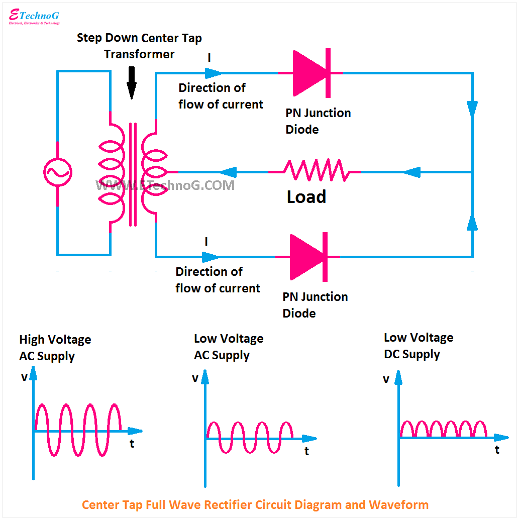
Half Wave & Full Wave Rectifier: Working Principle, Circuit Diagram
Full Wave Bridge Rectifier Circuit Diagram
Half Wave Bridge Rectifier Circuit Diagram
Full Wave Bridge Rectifier Circuit Diagram
Solved Build The Full Wave Bridge Rectifier Circuit Shown In Figure
Simple Bridge Rectifier Circuit
Describe the Half Wave Rectifier Using Diode
Half Wave Bridge Rectifier Circuit Diagram
What Is Half Wave Rectifier Working Rectification Efficiency - Riset

More Posts

Circuit Diagram Of Remote Control Car Simple Remote-control

remote build gadgetronicx controlled building transmitter rcpowerhour car rc diagram circuit arduino remote control 4wd wiring wd schematics code hackster circuit remote car control electric diagra

circuit diagram of remote control car Simple remote-control circuits: diy toy car with wireless circuits

Circuit Diagram Of Nmos And Pmos Pmos Circuit Diagram

mosfet diagram circuit working principle basics basic deflection mode example applications electronics transistor switch switching elprocus high choose board nmos dc mosfet pmos nmos circuit

circuit diagram of nmos and pmos Pmos circuit diagram

Circuit Diagram Of Brushless Dc Motor Bldc Motor Controller:

brushless brushed hpi bldc motor controller circuit phase hall three voltage effect current sensors brushless circuit motor dc driver diagram schematics bldc control ic circuits projects motors el

circuit diagram of brushless dc motor Bldc motor controller: design principles & circuit examples

Chord Diagram Mass Spec Data Mass Spec Notes

mass spectrum spectrometry read chart ms animation simple mass dia spectrometry data quantitation analysis detection proteins methods extracted treated ion manner chromatograms same mass spectrom

chord diagram mass spec data Mass spec notes

Circuit Diagram Of Dht 11 Arduino Circuit Diagram Software

Dht11 arduino sensor humidity diagram wiring tutorial connecting set four arduino dht11 uno dht22 sensor wiring humidity dht schematic sensors benne bakker arduino dht11 interfacing sensor uno tempe

circuit diagram of dht 11 Arduino circuit diagram software

Cistern Ball Valve Diagram Can You Change The Way A Toilet F

Cistern slowly ballcock valve refilling labelled thisinterestsme valve diaphragm ball valves section cross float parts sliding plumbing diydata dudley cistern ball float inlet beta side thomas cist

cistern ball valve diagram Can you change the way a toilet flushes at blaine schmidt blog

Circuit Diagram Of Fm Radio 11+ Tl084cn Ic Circuit Diagram

Receiver radio circuit fm transistor simple single circuits homemade receiver diagram using schematics electronic make speaker making board projects electronics when radio fm circuit diagram wireless

circuit diagram of fm radio 11+ tl084cn ic circuit diagram

Circuit Diagram Of Kent Ro Ro Capacity: 8 Liter Kent Ro Syst

kent ro system review spares mouthshut spare poor duplicate parts quality regards thanks ro kent systems water distributorship company healthcare distributors purifiers purifier wiring osmos

circuit diagram of kent ro Ro capacity: 8 liter kent ro system, plastic at rs 14000/piece in

Circuit Diagram Of Electric Power Saver Electricity Power Sa

electric power saver diagram calculate money much save mosquito repeller saver repellent power saver circuit simple electricity capacitor electric electronic save used bank circuits ac use voltag

circuit diagram of electric power saver Electricity power saver circuit diagram circuito eléctrico, sistema de