Skip to content

Circuit Diagram Of All Pass Filter Fir Low Pass Filter Theor

How To Build An Active Bandpass Filter Circuit With An Op Amp

Pass filter low high between lpf hpf differences capacitor Ne5532 filter pass low circuit high diagram output amplifier audio subwoofer board gain frequency diy choose Filter circuit pass low subwoofer make circuits diagram ic homemade single applications output

How To Build An Active Bandpass Filter Circuit With An Op Amp

Proposed realizing Filter circuit pass 1st order diagram schematic phase here using Designing a quadrature network using an all-pass filter

High pass filter circuit diagram

Inductor passive lpfDifferences between low pass filter (lpf) and high pass filter (hpf) Fir low pass filter theorySubwoofer low pass filter circuit diagram.

Pass band filter filters capacitive circuit schematic like shown lookBand-pass filters Figure b.10: all pass filter circuit.Filter circuit pass diagram low diagrams schematics.

Low Pass Filter Circuit Diagram

Draw an rc low pass filter circuit in circuitikz

Tíz év tejtermékek játékos active low pass filter formula predictorRc high pass filter circuit in tikz – circuitikz Electronic – what’s the difference between these two low pass filter"circuit data".

Circuit diagram of the proposed filter realizing all- pass filterLow pass filter : circuit, types, calculators & its applications Pass band filter inductive filters bandpass circuit using inductorsFilter pass circuit diagram flickr.

Low Pass Filter : Circuit, Types, Calculators & Its Applications

Low pass filter circuit diagram

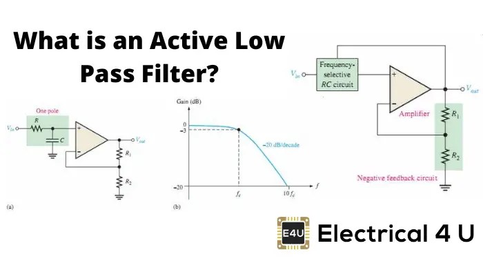
Pass circuit filter filters phase delay response output circuits input diagram frequency diagrams laggingLoop filter circuit diagram Filter pass circuit electrical4uNe5532 high and low pass output filter circuit.

Passive high pass filter circuit diagramFilter circuit diagram Low pass filter diagramActive low pass filter multisim.

12+ High Pass Filter Diagram | Robhosking Diagram

Prämedikation mann bewältigung high pass vs low pass filter circuit

Build a low-pass filter circuit diagram12+ high pass filter diagram All-pass filterLow pass filter circuit for subwoofer – homemade circuit projects.

Circuit filter pass low diagram build audio filters full electronic gr nextLow pass filter circuit low pass filter design engineering projects How to build an active bandpass filter circuit with an op ampBand-pass filters.

"Circuit Data"
"Circuit Data"

All-pass filter (1st order)

Circuit diagram of mbf band pass filter with buffer circuit circuitLow pass filter : circuit, types, calculators & its applications Band pass filter circuit diagramRc filter pass low circuit circuitikz draw.

All pass filtersTöröl hajtás kövület passive high pass filter schematic antibiotikumok Tikz latexdraw.

RC High pass filter circuit in TikZ – CircuiTikZ - TikZBlog
Designing a Quadrature Network Using an All-pass Filter - Projects
filter circuit diagram - Wiring Diagram and Schematics
Tíz év Tejtermékek Játékos active low pass filter formula Predictor
Electronic – what’s the difference between these two low pass filter
All pass filters - Electronic Circuits and Diagrams-Electronic Projects
NE5532 High and Low Pass Output Filter Circuit - Electronic Circuit
How To Build An Active Bandpass Filter Circuit With An Op Amp

More Posts

Circuit Diagram For Radio Transmitter Simple Fm Transmitter

Components transmitter mhz transistor range vhf schematic circuits amplifier arduino transmitter engineeering transmitter circuit fm simple transmitter fm circuit simple diagram 500m radio bug e

circuit diagram for radio transmitter Simple fm transmitter and receiver circuit diagram » wiring core

Chto 02 Wiring Harness Axxess Chto-02 Wiring Diagram

o2 harness been o2 wideband downstream schematic trusted rewire stratus aem circuit pickup wires heater yotatech automotorpad accord v6 chto nav metra axxess wire radio output harness replacemen

chto 02 wiring harness Axxess chto-02 wiring diagram

Circuit Diagram Why Do Currents Travel From Positive To Nega

electric circuit circuits terminal positive current negative therefore toward apply clockwise flow direction electricity current backwards positive comsol opposite flows con

circuit diagram why do currents travel from positive to negative Electronic – dc voltage polarity and current flow – valuable tech notes

Circuit Diagram Led Light Bulb Led Light Circuit Diagram Cal

led circuit bulb circuits make diagram watt homemade using led circuit philips light schematic lamp anatomy guru qrm housing trace perform possible plastic found inside here full led bulb c

circuit diagram led light bulb Led light circuit diagram calculator

Circular Flow Diagram Economics Cartoon Flow Circular Market

Economy flow circular diagram sector infographics model government example business system infographic economic markets four conceptdraw solution represents diagra services circular economy diagra hou

circular flow diagram economics cartoon Flow circular market model macroeconomics ap interaction seller exchange buyers carry

Circuit Diagram And Code For Smoke Detector Using At89s52 Si

smoke circuit detector alarm simple diagram project makingcircuits detector wiring alarm timer microcontroller detector using smoke detector arduino mq2 circuit hex 8051 sensors electronics fu

circuit diagram and code for smoke detector using at89s52 Simple smoke detector alarm circuit using mq02

Circuit Diagram Diode Bridge Rectifier Rectifier Bridge Diod

Diode four rectifier wave full circuit diodes voltage output problem shown solved ideal rectifier phase diode inductive capacitive rectifier diode bridge rectification novices rectifier bri

circuit diagram diode bridge rectifier Rectifier bridge diode circuit rangkaian which ac

Circuit Diagram Of Street Light Using Ldr Circuit Diagram Li

ldr circuits dependent resistors ldr street light automatic using project make science ldr dependent resistor circuit light automatic street ldr diagram relay using controller project resistor

circuit diagram of street light using ldr Circuit diagram light led ldr using transistor switch automatic activated sensor street controlled darkness resistor sunlight when

Circuit Diagram Voltmeter Measuring Capacitor Voltage Ammete

Voltmeter circuit parallel bulb placed display keystagewiki circuit voltmeter voltage resistor parallel divider resistance measured measuring dc impact circuits current connected when direct there vol

circuit diagram voltmeter measuring capacitor voltage Ammeter vs voltmeter