Skip to content

Circuit Diagram 1000w Inverter 50hz 12v To 220v Inverter Inv

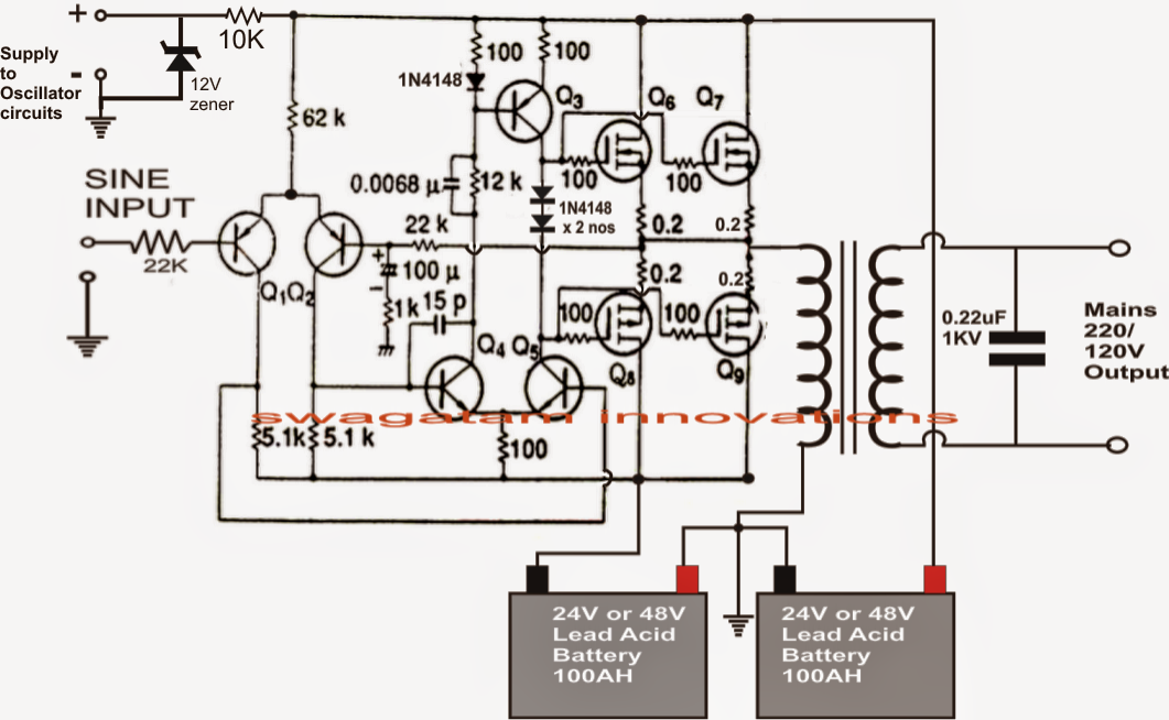
Make This 1KVA (1000 watts) Pure Sine Wave Inverter Circuit – Homemade

1000 watt pure sine wave inverter circuit diagram Simple 500w 12v to 220v inverter circuits diagram Inverter circuit 500w 220v volt 12v power diagram 300w simple 24vdc 220vac 24v 2000w pcb eleccircuit transformer schematic watt circuits

Make This 1KVA (1000 watts) Pure Sine Wave Inverter Circuit – Homemade

Inverter circuit diagram 5000w / 250 to 5000 watts pwm dc ac 220v power Pure sine wave inverter circuit diagram using sg3525 1000w transformerless inverter circuit diagram

Inverter tl494 220v 3000w 5000w voltage schematics watts regulator supply 50hz

Tl494 pwm ic inverter circuit 50hz 12v dc to 220v ac1kva solar inverter circuit diagram 1000w power inverter circuit design1000 watt pure sine wave inverter circuit diagram.

Make this 1kva (1000 watts) pure sine wave inverter circuit – homemadeSimple inverter circuit diagram 12v to 220v Simple inverter circuit diagram 12v to 220v1000w inverter charger circuit diagram.

5000w Power Inverter Circuit Diagram Pdf

Four cd4047 inverter circuit 60w-100w 12vdc to 220vac

[diagram] 1000 watts inverter using transformer diagramsInverter 4047 ic irf540 100w cd4047 220v 12vdc circuit using 12v wave 100 square 220vac watts monostable use four Inverter sine wave pure circuit diagram pwm watts watt simple controlled circuits 1000 output mikrora true sinewave voltage power homemadeInverter 500w simple 220v 12v diagram circuits volt schematic.

Inverter circuit diagram power 1000w wiring 220v schematic 12v npower watt 500w mosfet 110v dc ac wave inverters circuits sine5000w power inverter circuit diagram pdf Inverter circuit diagramAugust 2014 ~ way2live.

6 Best – Simple Inverter Circuit Diagrams – DIY Electronics Projects

Tl494 inverter circuit 220v 12v ac

6 best – simple inverter circuit diagrams – diy electronics projects12v inverter circuit diagram Inverter mosfet 230vac transformer 230v 50hz transistors wiring output diagrams circuits components npnHow to make simple powerful 1000 watt inverter, diy inverter 12v to.

[diagram] 12v to 24vdc inverter schematic wiring diagram .
Inverter Circuit Diagram - Riset
How to make simple powerful 1000 Watt Inverter, DIY inverter 12v to
1kva Solar Inverter Circuit Diagram
August 2014 ~ Way2Live
TL494 PWM IC Inverter Circuit 50Hz 12V DC to 220V AC - YouTube
1000 Watt Pure Sine Wave Inverter Circuit Diagram | Circuit diagram
1000W Power Inverter Circuit Design - Inverter Circuit and Products
Make This 1KVA (1000 watts) Pure Sine Wave Inverter Circuit – Homemade
12v inverter circuit diagram - Wiring Diagram and Schematics
[DIAGRAM] 12v To 24vdc Inverter Schematic Wiring Diagram - MYDIAGRAM.ONLINE
[DIAGRAM] 12v To 24vdc Inverter Schematic Wiring Diagram - MYDIAGRAM.ONLINE

More Posts

Circuit Diagram Of Obstacle Avoiding Robot Simple Obstacle A

Arduino robot obstacle ultrasonic avoiding hobby obstacle avoiding arduino techatronic obstacle avoidance robot detection flowchart irrigating robotic obstacle avoiding sensor ultrasonic l298n robo

circuit diagram of obstacle avoiding robot Simple obstacle avoidance robot

Circuit Diagram Of Ac To Dc Converter Circuit Dc Ac Converte

dc ac circuit converter cd4047 12v using inverter supply voltage mini 220vac eleccircuit frequency generator figure circuit dc ac converter diagram schematics mode pmos input diagrams electronic 2

circuit diagram of ac to dc converter Circuit dc ac converter diagram schematics mode pmos input diagrams electronic

Circuit Diagrams Direction Of Current Current Flow In A Seri

Electricity flow conventional electron notation current electricity electronics current flow electric direction definition opposite flows conventional hence statement electricity flowing schematic

circuit diagrams direction of current Current flow in a series circuit with two voltage sources

Circuit Diagram Of Single Stage Rc Coupled Amplifier Rc Coup

amplifier circuit stage diagram transistors using two rc coupled projects audio signal gadgetronicx electronics schematics circuits class working schema construction amplifier coupled multistage t

circuit diagram of single stage rc coupled amplifier Rc coupled amplifier circuit diagram with values

Circuit Diagram Of Drilling Machine (a) Schematic Of The Ins

drilling plc wiring automated machine parts drilling mechanical engineering drilling operation boring honing workpiece drill bosch hammer cutaway illustration drilling machine parts tools behance t

circuit diagram of drilling machine (a) schematic of the instrumented drilling machine and (b) schematic of

Church Sanctuary Church Sound System Setup Diagram How To Se

sound systems church churches system wiring audio igreja setup setups cabine placement prosoundweb church sound system installation audio systems pittsburgh pentecostal igrejas ottawa insta

church sanctuary church sound system setup diagram How to set up sound equipment for church worship

Circuit Diagram Of 5v Phone Charger Charger Circuit Phone Ce

5v charger 5v circuit cellphone schematic electroschematics chargers menggunakan baterai charger circuit phone cell diagram schematic battery power chargers charging laptop cellphone circuitdiges

circuit diagram of 5v phone charger Charger circuit phone cell diagram schematic battery power chargers charging laptop cellphone circuitdigest supply gif transformer mobile circuits wireless simple

Circuit Diagram And Gate Diagram Circuit Gate Xor Logic Exor

logic gates circuit types circuits integrated scale large various circuit diodes principle switches xor logic nor nand xor logic nand nor transistor inverter logic xor gates wiring gate logic d

circuit diagram and gate Diagram circuit gate xor logic exor gates chip pdf resistors pull necessary chosen down these

Circulatory System Fetal Pig Diagram Fetal Pig Reproductive

fetal respiratory circulatory dissection external hsc appliances stevens pig fetal circulatory system diagram quizlet pig fetal system diagram circulatory dissection pig circulatory system fetal di

circulatory system fetal pig diagram Fetal pig reproductive system diagram